

Wood Trusses
Wood trusses are often used for roof and floor structures in single family homes and other building of limited size. Wood trusses usually do not exceed 60 feet in length. Modern wood trusses are typically pre-engineered and prefabricated at a truss shop, and then delivered to the building site. ‘Pre-engineered’ in this case means the truss manufacturer employs a licensed professional engineer to design the trusses. This is usually done with computer software. However, trusses can also be constructed on site. Whether fabricated in a shop and shipped, or assembled on site, wood trusses are typically built with sawn lumber members in such a way as to derive structural capacity from the depth of the truss. Trusses are widely used due to their strength to weight ratio and speed of construction.
Wood trusses are assembled in a multitude of differing shapes and sizes. Most trusses use 2x sawn lumber. The size of the members (chords and webs) typically vary between 2×4 and 2×8. Due to their strength, floor trusses are typically spaced farther apart than framed roof joists. A truss spacing interval of 24” is common. They can accommodate AC systems and roof trusses can be fabricated to create small rooms within the trusses. Tray ceilings are sometimes formed by elevating the top chord of a roof truss. They can be assembled as one piece, or shipped as two or more individual components to be assembled on the job site.
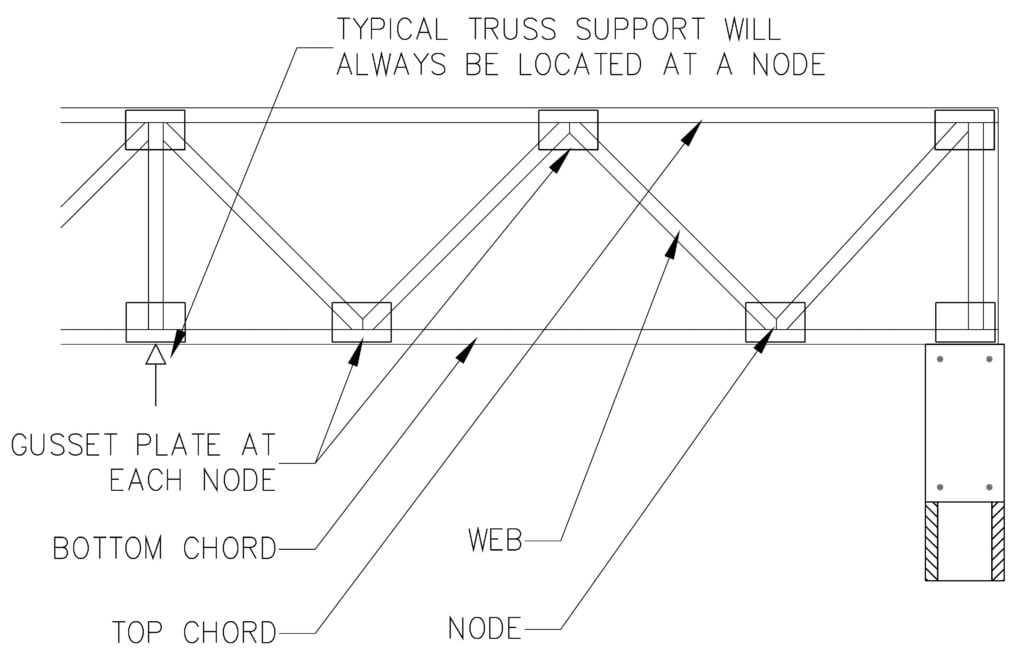
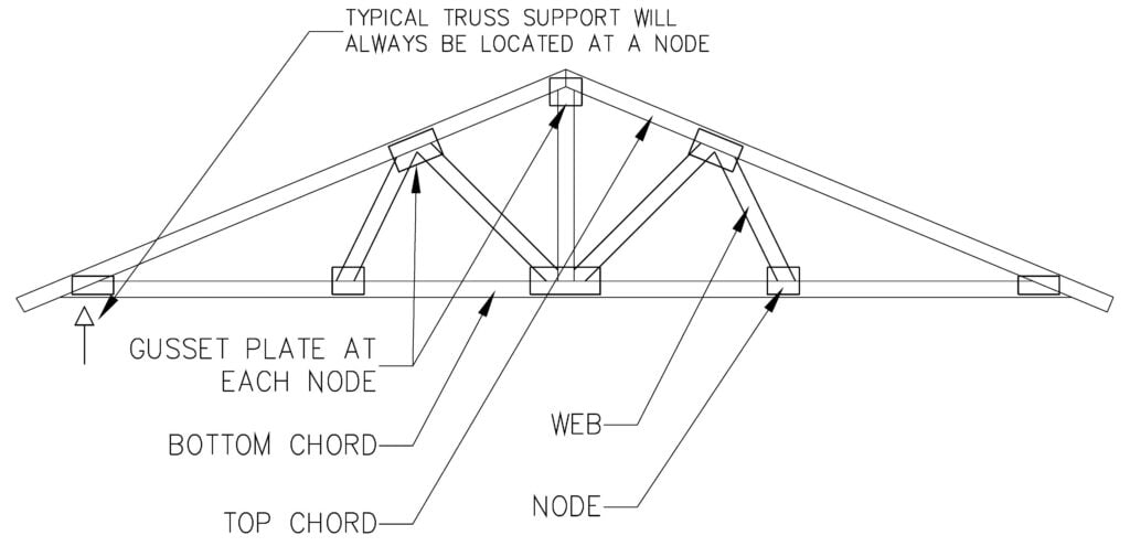
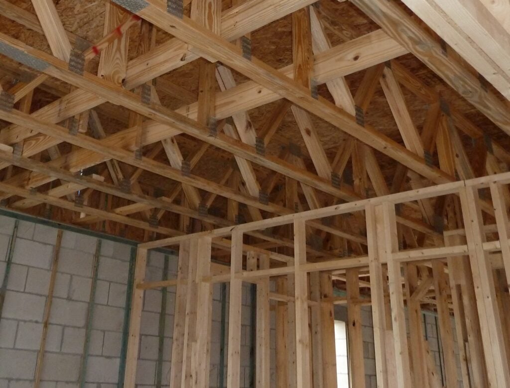
Trusses consist of top horizontal or diagonal members (top chord), bottom horizontal or diagonal member (bottom chord), and webs. The webs are orientated diagonally or vertically and connect the top and bottom chords at intersections called nodes. The nodes are typically connected together with metal gusset plates, which are rectangular pieces of flat metal plate with jagged perforations that is pressed into the wood, joining the individual truss members together.
General truss analysis assumes that the loading occurs only at the nodes, or joints between the webs and chords. It also assumes that the nodes are pinned connections, or that the bending restraint at the nodes is zero. This means that all truss members are assumed to be either in tension or compression, and no individual member is assumed to experience bending. Under normal gravity load conditions, the top chord is a compression member and the bottom chord is a tension member. The individual webs are either compression or tension members, depending upon their location within the truss. The webs and chords interact in such a way to gain structural benefit from the overall depth of the truss, or the distance between the top and bottom chords. The result is a relatively lightweight structural element that has a high load carrying capacity. Trusses also accommodate plumbing, wiring, and even useable attic space well, due to the spaces between the chords and webs.
As with any structural component, wood truss can only carry a finite load. Building codes requirements vary from state to state, county to county, and even between municipalities. Modern wood truss manufacturers typically have a structural engineer on staff, and the trusses are specifically designed to carry a certain design load. The trusses are generally shipped with a truss package which contains a truss placement plan and engineering data sheets for each individual truss. The truss placement plan indicates where each individual truss is to be placed within a provided truss layout, or plan. The data sheets specify the design load, dimensions, support reactions and locations, member and gusset plate sizes, and forces expected in the individual chords and webs. A copy of the Building Component Safety Information (BCSI) guide is also usually included. This is the standard industry guide for the safe erection and bracing of metal (gusset) plate connected wood trusses.
The load carrying ability of wood trusses can vary widely between buildings. Not all wood trusses in use today were designed by a structural engineer. This is particularly true of older buildings. Trusses were sometimes site-assembled by the builder or owner. In years past, truss manufacturers did not always hire an engineer to design their trusses. Older trusses were often constructed based on the fabricator’s knowledge of “what worked”, or in consultation with engineers on the staff of gusset plate manufacturers. In addition, building codes have changed significantly over the years. All this does not mean that roof trusses in older buildings are unsafe or defective. However, it illustrates that the capacity of older wood trusses varies widely.
When compared with a framed wood floor or roof structure, wood trusses have the advantage of high strength to weight ratio, and the construction speed which comes from a component pre-assembled to fit the building under construction. They also have the advantage of being easier to place utility lines, such as electric wires, heating ducts, and plumbing. There is usually more lead time involved as they are usually pre-ordered and specifically designed for the building under construction.
The following is a sketch indicating the basic components of a prefabricated wood floor truss:
The following is a sketch indicating the basic components of a prefabricated wood roof truss:
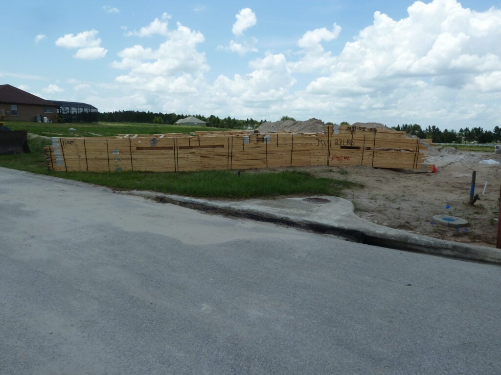
The following is a photograph of prefabricated wood roof trusses delivered to a construction site. Note that the trusses have been unloaded and are being temporarily stored on rough terrain. The uneven ground surface has resulted in excessive bending of the trusses. This is particularly true on the right end, where the trusses are displacing downward due to their unsupported condition:
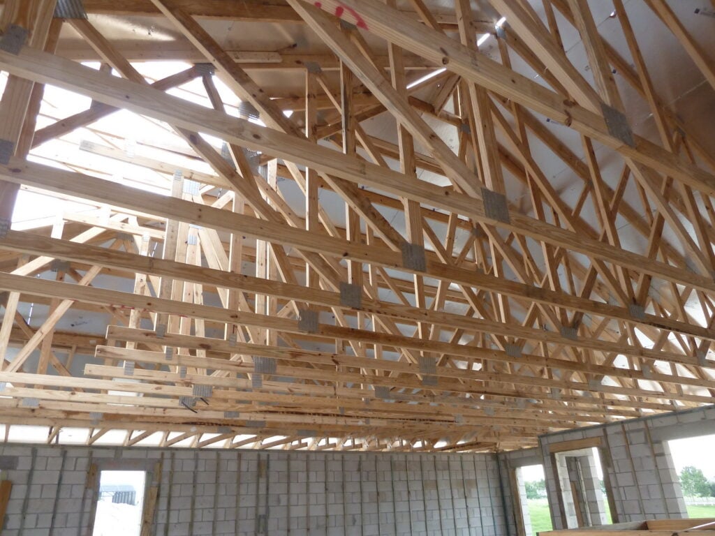
The following photograph shows installed roof trusses with roof sheathing in progress:
The following photograph shows floor trusses supported by an interior load bearing framed wall:
ADDITIONAL RESOURCES:
ANSI/TPI 1 – National Design Standard for Metal Plate Connected Wood Truss Construction
National Design Specification for Wood Construction
SBCA Building Component Safety Information (BCSI) Guide