

Continuous Footings
Continuous footings, also referred to as “strip” or “spread” footings, are concrete footings most often used to support the load bearing walls of a building. This type of footing is shaped as a long rectangular box that is continuous below the supported wall, that with the wall forms the base of an upside down “T”.
The size of continuous footings varies with the loading and soil conditions. However, a thickness range of 12” to 16” and width range of 24” to 30” are common with one or two story buildings of lighter construction. The area of soil or ground covered by the footing and the bearing capacity of the underlying soil determines the footing’s support capacity. Wider and sometimes thicker strip footings are required to support heavier loads.
Steel reinforcement is usually provided in strip footings and varies with the design loads and the local building code. The reinforcement typically consists of continuous or “longitudinal” steel bars placed near the bottom of the footing. They may also have shorter steel bars (the width of the footing minus several inches for concrete cover) placed, at regular intervals, perpendicular to and immediately above or below the longitudinal bars. These are sometimes referred to as “transverse” bars. The reinforcing steel provides additional strength and crack control.
The top of a continuous footing is usually at least several inches beneath the finished grade, or ground. This means that whatever material that is placed directly on top of the footing must be able to withstand the constant presence of moisture. Concrete is just such a material that is almost impervious to rot. So, it is usually CMU block but sometimes reinforced concrete walls that are placed on the footing. These walls can be continous to the roof above, or they can terminate just beneath a concrete slab or elevated framed first floor structure.
The supported wall is not always centered on continuous footing. An example where the wall is often placed off-center is a free-standing retaining wall. A retaining wall “retains” or holds back soil. These walls are often placed so that the footing and wall form an ‘L’. The weight of the retained soil (bearing on the bottom leg) restrains upward movement or overturning of the wall and buried footing, thus increasing its ability to “retain”. The soil weight also reduces the likelihood that the footing will move or slide horizontally by increasing the frictional force between the soil and the bottom of the footing.
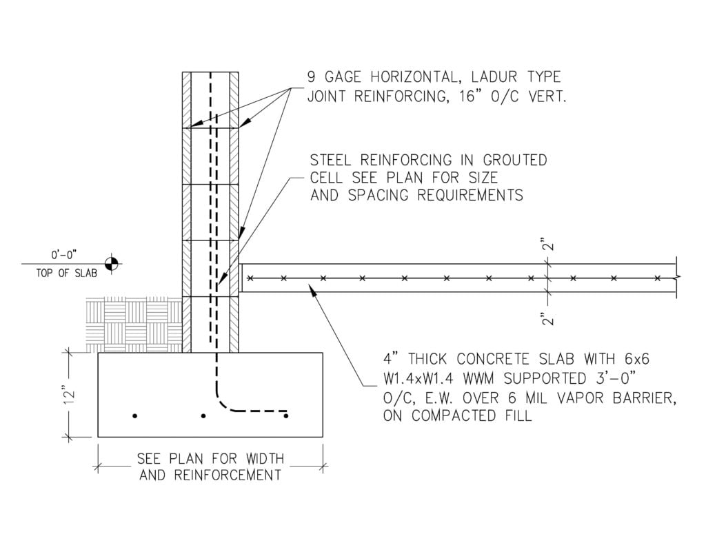
The following sketch is an example of a concrete strip footing supporting a typical CMU residential exterior wall. The slab on grade shown is sometimes referred to as a “floating slab” as it is not structurally connected to the wall. Alternatively, the slab may be placed over the CMU, and the wall started again on top of the slab edge:
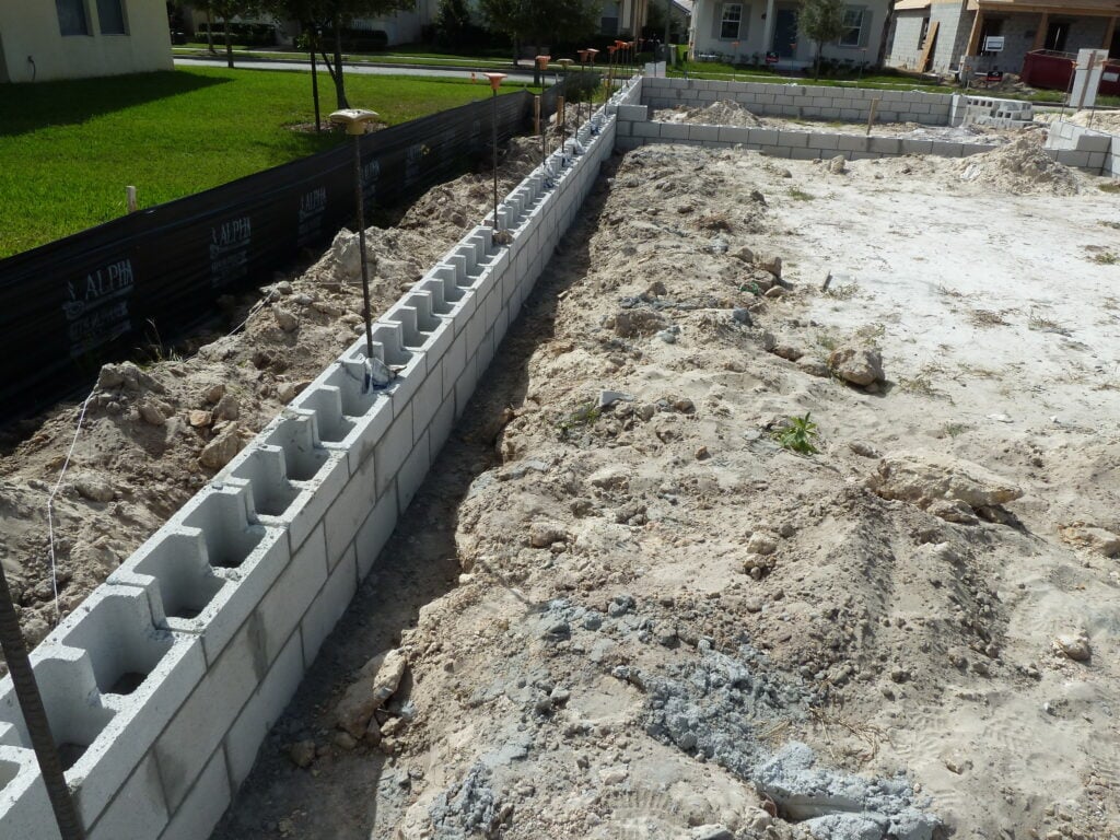
The following is a photograph showing the early construction of a CMU wall supported by a continuous footing. The footing itself is covered by soil, and is not visible in the photograph. The interior slab has not yet been prepared or placed. The vertical steel bars protruding at the top of the wall were placed with and protrude from the top of the footing. They are intended to lap with the vertical steel bars dropped into the top of the wall after the CMU wall block is in place:
ADDITIONAL RESOURCES:
ACI 117 – Standard Specification for Tolerances for Concrete Construction and Materials
ACI 318 – Building Code Requirements for Structural Concrete
ACI 332 – Residential Code Requirements for Structural Concrete