

Framed Floor Structure
Sawn or engineered lumber joists are often used to frame residential floors. The structure of a typical wood framed floor typically involves three primary structural components. The first of these is the subfloor decking (or sheathing). This forms what is sometimes referred to as the “subfloor” located just beneath the finished, exposed flooring such as carpet or tile. The floor decking spans across and is supported by the floor joists. The second primary component of a framed floor structure is the floor joists. Floor joists are spaced at regular intervals and are typically sawn or engineered lumber. In some floor structures, beams support the floor joists and if existing, could be considered the third primary component of a floor structure. Finally, the beams and or joists are supported by load bearing walls and or columns. Columns are often used to support heavy gravity loads carried by beams.
Floor decking typically consists of sheathing. The sheathing may be plywood or oriented strand board (OSB). Older buildings will often have sawn lumber boards used for the floor decking. The decking spans over the floor joists, and therefore must be of sufficient strength and stiffness to transfer any point load to the adjacent floor joists without failure or excessive deflection. Wider floor joist spacing requires thicker and stronger floor decking. The thickness of plywood or OSB sheathing varies with the type and application, but 3/4″ is common for floor decking. The width and thickness of individual wood planks is significant with regards to point loads. When loads are applied over an area, 2×4 decking is as capable as 2×6 or 2×8 decking. However, if a point load happens to be applied to only one board, then a wider board is obviously stronger than a narrow board. This concept is not as significant if adjacent floor planks interlock with each other by a tongue and groove mechanism. This has several advantages: point loads are transferred to adjacent boards and movement is restrained across the boards, resulting in a quieter, tighter, and smoother floor.
The floor joists provide support to the floor decking or planks. The joist type, size, grade, and spacing is determined by their unsupported length (span), the support conditions, and loading conditions. Floor joists are supported by beams or load bearing walls. The beams may be composed of sawn lumber, LVLs, reinforced concrete, CMU, or structural steel. The floor joists may bear on the top, or be attached to the side of a beam. The beam capacity is determined by its unsupported length, or span, and the tributary area of the floor joists it supports. A typical floor beam is supported by a load bearing walls or columns. The load bearing walls may be exterior (perimeter) walls, or located at the interior. Walls and columns are supported by foundations, lower walls, or beams.
When compared with a wood trusses, a floor structure framed with sawn lumber may have an advantage in that sawn lumber is readily available at a lumber yard, where trusses generally need to be pre-ordered. Also, sawn lumber is usually less deep, and thus use less vertical space within the building. However, it is more difficult to place utility lines, such as electric wires, heating ducts, and plumbing in a framed floor structure perpendicular to the joists. This is because trusses have spaces between the webs and chords which allow placement of utility lines.
Finish flooring such as carpet, tile, or vinyl is applied to and supported by the floor decking or sheathing. The finish flooring generally has no structural support value and is not considered to be a part of the ‘floor structure’. However, it can be affected by a problem with the floor structure, and vice versa.
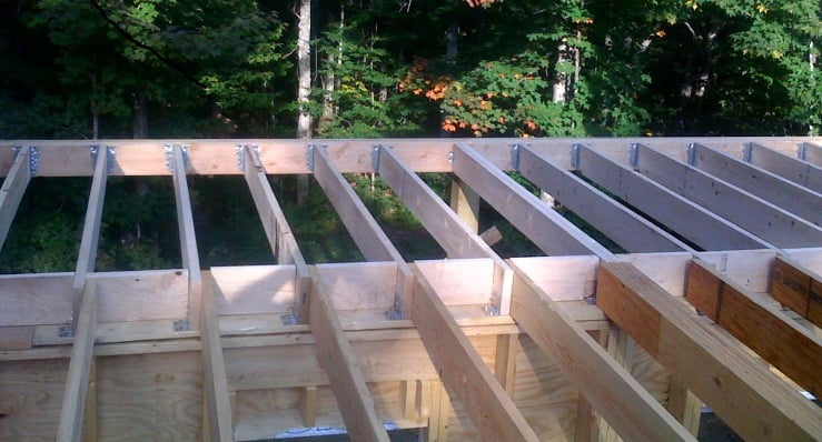
The following is a photograph of a framed floor structure under construction. Standard dressed 2×8 sawn lumber and LVLs were used for the joists. The LVLs are visible at the lower right hand corner, including a triple ply beam intended to support a load bearing interior wall (not shown). The rear joists are secured to the face of the triple 2×8 beam (at rear) with metal connectors and are supported at the other end by the rear 2×6 framed exterior wall. The interior joists are also supported by the rear exterior wall, and exterior blocking exists between the end-to-end joists:
ADDITIONAL RESOURCES:
National Design Specification for Wood Construction
Timber Construction Manual