

CMU Load Bearing Walls
The exterior walls of many homes and other structures are constructed using concrete masonry unit (CMU). The base material of CMU, or ‘block’ masonry is concrete. This is different than brick masonry whose base material is typically clay or shale. Brick is also used for home construction, often in an aesthetic or cladding capacity. While similarities exist between brick and block masonry construction, brick masonry is not discussed further here.
The basic components of a reinforced CMU wall are block, mortar, steel, and grout. CMU block is available in many different shapes, sizes and strengths. Common block sizes are between 2 and 24 inches, in multiples of 2 inches. The actual dimensions of the blocks are normally 3/8 inch less than the given nominal dimension. This allows an even measurement when 3/8 inch of mortar is placed between the blocks during construction. The blocks may be solid, but are often made with holes. The most common block used for home construction is an 8x8x16 inch nominal block with two holes. The holes serve several purposes including weight and material savings, improving the thermal insulation properties of the wall, and allowing steel and grout to be installed during construction. A typical CMU block strength is 1900 psi, but CMU may be available between 1250 and 4800 psi. It should be noted that block strength is only one contribution to the strength of the completed masonry structure. Block strength, mortar type, grout strength, structure layout, quality of workmanship, and steel grade, size and location are all contributing factors to the strength of a completed masonry structure.
The mortar is a mixture of water, cement, hydrated lime, and sand that is placed between the blocks during erection. The mortar binds the blocks together and provides an even bedding surface for compressive load transfer. Different types of mortar are used, each of which has varying characteristics and trade-offs between strength, flexibility, and bond.
In areas of expected significant lateral (wind or earth) or uplift (wind) loads, CMU walls are constructed with reinforcing steel. The steel is necessary because concrete, including concrete masonry, is relatively weak in tension. The typical tensile (stretching) capacity of concrete is only 10%-15% of its compression capacity. Steel, on the other hand, is strong in tension, and is placed so as to engage tensile loads expected to occur within the CMU structure. Reinforcement steel should normally be placed continuously (lapped at joints) for proper load transfer. The required length of a lap is sometimes referred to as ‘development length’, and depends upon the grade of the steel, strength of the surrounding grout or concrete, and the concrete or grout cover.
Vertical reinforcement steel is often placed in grouted ‘filled’ cells and at tie columns. A filled cell consists of a vertical steel bar placed within a CMU cavity, which is then filled with grout. The cell steel is usually centered (within the wall thickness) and placed in the block cavities (cells) at regularly spaced intervals. Tie columns are reinforced grouted columns formed within the masonry wall and used to support higher gravity, uplift, or lateral loads. A tie column is found within the wall itself, with masonry immediately adjacent to one or both sides. A reinforced concrete (non-masonry) column is normally free standing, with infilled masonry sometimes placed against it. For steel continuity, vertical “lap” bars with 90 degree “hooks” are placed in the foundation at regular intervals prior to the slab concrete placement. This results in vertical bars protruding at regular intervals from the top of the new footing / slab, to be lapped with the vertical filled cell or tie column steel.
Two loads which vertical steel in a CMU wall resist is uplift from the roof and bending from wind against the wall. Vertical steel resists uplift by preventing the wall from pulling apart under high wind loads. The uplift forces are resisted through a continuous load path from the foundation to a tie beam or bond beam to which the roof trusses are attached. Vertical steel also resists bending induced by wind forces against an exterior wall. These forces are collected and transferred to the beam or foundation below and beam above.
Horizontal steel is placed in bond beams or tie beams. The beams are usually placed at the top of a CMU wall. Horizontal steel may serve several purposes within a CMU wall. Perhaps most obvious would be the support of gravity loads on a beam spanning over a door or window opening. It may transfer uplift loads from roof trusses to the vertical steel in tie columns or filled cells. Horizontal steel may restrain lateral loads from filled cells (or tie columns), or restrain diaphragm chord tensile forces at perimeter tie beams or bond beams.
Small diameter (~3/16 inch) ladder or truss type horizontal joint reinforcement is also used as horizontal reinforcement steel. This steel is placed between masonry courses (embedded in the mortar between two horizontal layers of block) for crack control, and may be specified in stack bond masonry for structural reasons. Dur-o-wal is a manufacturer of this type reinforcement and is also a generic term used for horizontal joint reinforcement.
Grout is similar to concrete except for aggregate size and slump. The aggregate size is smaller to allow the grout to flow through the wall or filled cell. Slump can be thought of as the viscosity of the grout, or how much it spreads out when a certain filled container is lifted from a flat surface. Grout is a mixture of cement, sand, small stones, and water. Admixtures are sometimes used to increase slump or delay hardening. In the case of a filled cell, the grout is pumped into the wall, filling the hollow block cores surrounding and encasing the vertical steel bars.
A CMU or concrete wall (covered or finished on both sides) can generally be distinguished from a wood framed wall in several ways. First, a CMU wall is more ‘solid’ and less prone to vibration when struck. Second, a wall framed with 2×4 or even 2×6 studs is obviously thinner than a typical 8” nominal masonry wall. Also, cracks in a CMU wall often occur in an 8 inch ‘step’ pattern, following the profile of the individual blocks. The exterior side of CMU walls will sometimes have stucco directly applied, or they can be simply painted. The interior finish side of a CMU wall often has vertical wood furring strips attached. Interior drywall or other wallboard material is attached to the furring strips, and the gaps between the furring strips are sometimes sprayed with cellulose or other insulation.
There are several advantages and disadvantages of CMU block construction as compared to wood framing. Perhaps the biggest advantages to building with CMU are the superior resistance to moisture (rot), insects, and fire. Another advantage is protection and strength. Properly reinforced and constructed CMU walls are solid, strong, and durable. Disadvantages include reduced thermal efficiency and the increased potential for cracking from material shrinkage, moisture and thermal effects, and settlement.
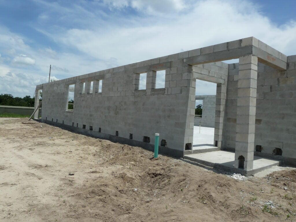
The following is a photograph of a CMU exterior wall of a home under construction. Note the “cleanouts” placed at regular intervals along the bottom of the wall. These allow the removal of mortar and debris and the vertical bar in the wall to be tied off with the bar protruding from the slab. This helps to keep the vertical steel in position during grouting. The cleanouts will be covered with plywood or another form prior to grouting:
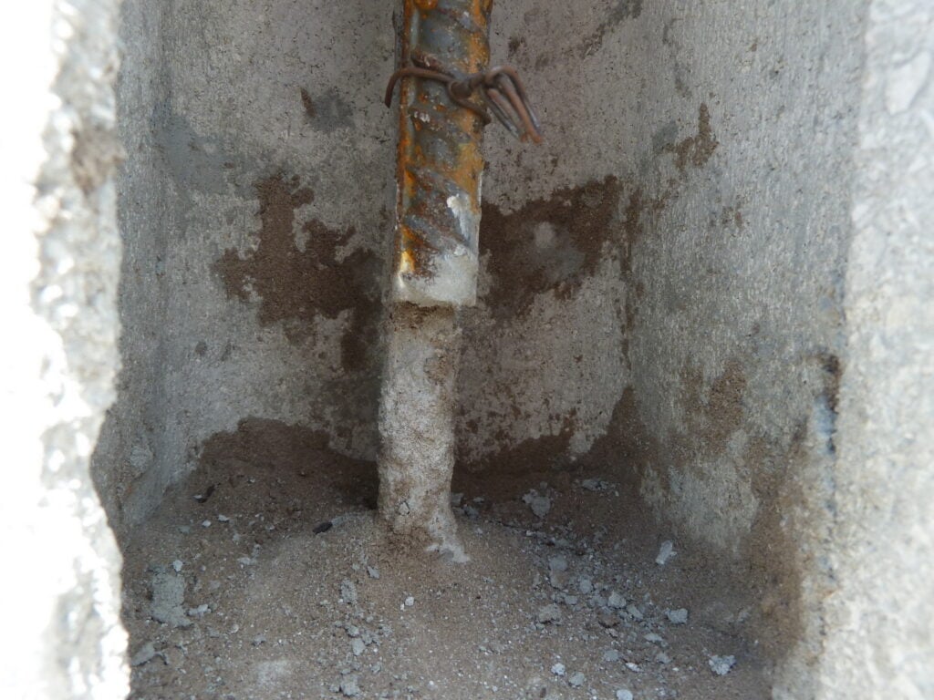
The following is a close up photograph of a CMU cleanout. The vertical #5 (5/8-inch diameter) steel bar (in front) is the bottom of a long steel bar with a 90 degree standard hook in the bond beam above (not shown). The bar behind protrudes from the concrete monolithic foundation. The two bars are tied together, with approximately 2″ of available lap lost by the steel placement shown. The sand and mortar at the bottom of the cleanout should be more thoroughly removed from the footing/slab before the cleanout is covered and the wall grouted:
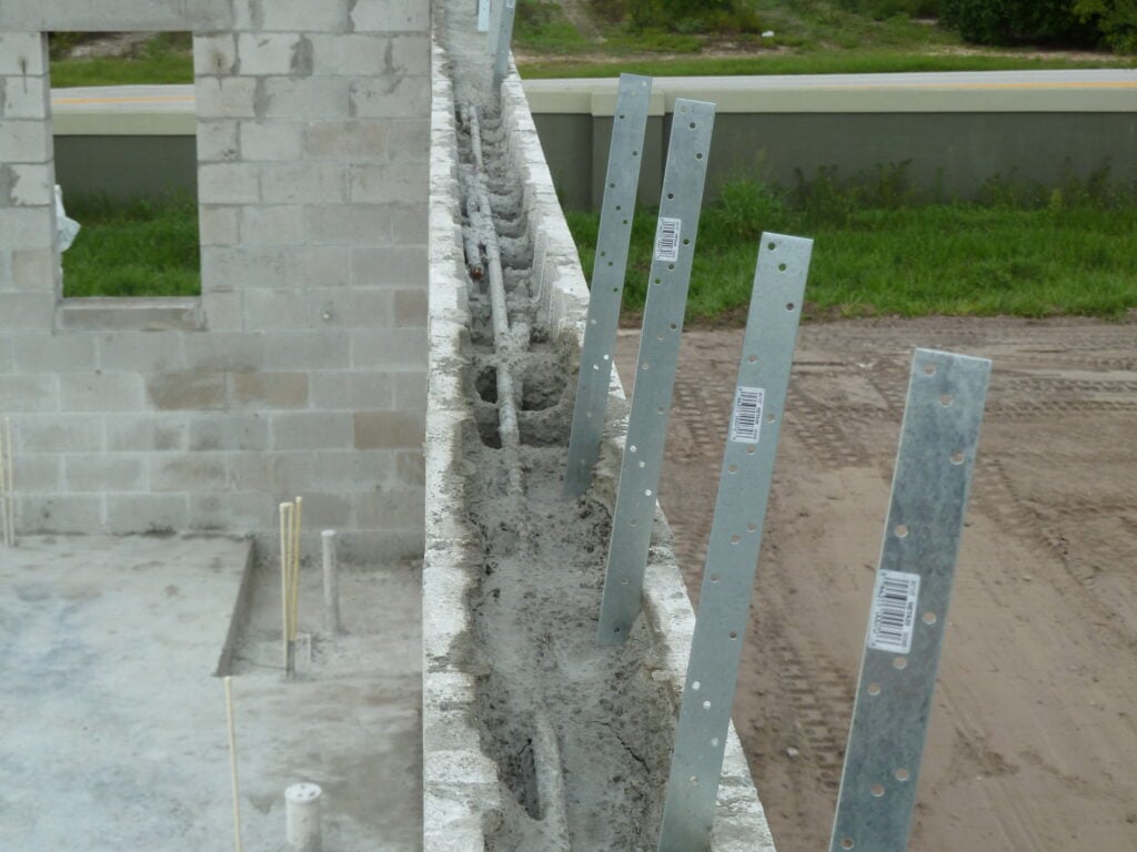
The following is a photograph of a CMU bond beam being grouted. Note the horizontal steel, the embedded steel truss straps, and the 90 degree standard hooks at the top of the vertical bars:
ADDITIONAL RESOURCES:
ACI 530 Building Code Requirements and Specifications for Masonry Structures
ASTM C476 Standard Specification for Grout for Masonry
ASTM C270 Standard Specification for Mortar for Unit Masonry