Bending or Moment
Most people already have an accurate concept of bending, or moment. Someone drawing a string back on a bow to shoot an arror applies a bending force within the bow…the hand holding the bow acts as a point load on a simply supported member. Someone holding a wood stick at each end and breaking it over their knee first induced a bending in the stick. The point of maximum bending would be where the support hand met the bow, or the knee met the stick. Bending is one of the primary considerations in beam design, together with shear and deflection. It is also a factor in the design and analysis of many other components including slabs, foundation, connections, etc.
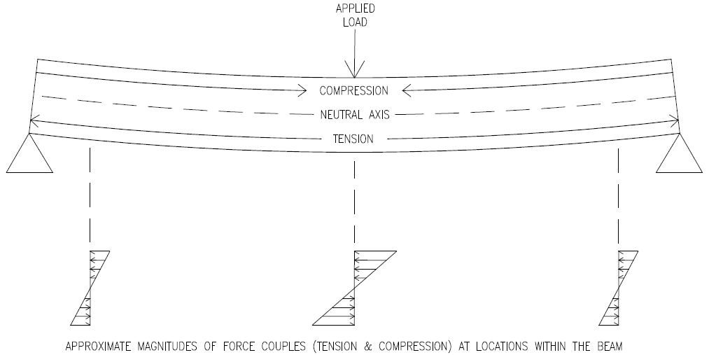
In engineering terms, bending can be described as an internal force couple, usually applied to a beam by an exterior force, such as gravity. In the above stick scenario, the stick is the beam and the exterior force is a point load applied by the knee. The force couple results from two opposing forces within the cross section of the stick. One force results from the compression, or squeezing, induced in the wood closest to the knee. The other force results from the tension, or pulling, induced in the wood furthest from the knee. In a square or rectangular stick, both areas equal 1/2 the cross sectional area of the stick.
Both compression and tension can be thought of as a stresses, or pressures inside the wood member. While there are many units of measurement, stress can be expressed in lbf per square inch (psi). A stress multiplied by the area it affects equals the total force. The stress experienced by the stick varies across the stick’s cross section. In this case, the maximum compression is experienced by the wood in contact with the knee. And the maximum tension is experienced by the wood opposite but directly over the knee. These stresses decrease to zero at the neutral axis, or center of the stick’s cross section.
Moment diagrams reflect the amount of moment at any given point along the length of a beam. They depend on load and support distribution. For instance, in a simply supported beam with a single point load in the middle, the moment diagram is a triangle reaching its maximum at the point load and tapering to zero at each end.
A visual representation of the actual bending stress within any particular cross section of the rectangular beam takes the shape of a lop-sided hourglass, or a vertical line with a diagonal line crossing it at its midpoint. The bending stress is thus maximum at the top and bottom, and zero at the middle of the cross section. These internal stresses vary along the length of the beam in accordance with the moment diagram discussed above.
In concrete beam construction, long steel bars are placed at the bottom of the typical beam to resist the tensile forces associated with bending. This is almost always necessary because concrete’s tensile strength is usually only about 10% of its compressive strength. Steel is also sometimes placed at the top of a concrete beam to increase the compressive strength as well.
Bending is a primary consideration in beam and other component design. It can be precisely analyzed, predicted and accounted for with math and knowledge of material strength, section capacity, expected loads, span, safety factors, etc